Gear reducer motors—also known as gearboxes or geared motors—serve as fundamental drive units across industrial manufacturing and micro-automation systems. By combining a high-speed electric motor with a speed-reducing gear train, these drives decrease output shaft speed while multiplying torque output.
Whether specifying heavy-duty industrial speed reducers or precision micro DC gear motors for OEM equipment, selecting the correct gearing layout and following proper installation guidelines ensures long-term system reliability.
Common Gear Reducer Motor Types and Industrial Applications
Gear reducer motors are essential drive components across diverse industries, including packaging machinery, printing presses, corrugated board production, automated storage and retrieval systems (ASRS), textile finishing, and chemical processing.
Different gearing designs suit specific speed, space, and torque requirements:
- Coaxial Helical Gear Reducer Motors: Feature aligned input and output shafts. They deliver high mechanical efficiency, quiet power transmission, and smooth operation under continuous loads.
- Parallel Shaft Helical Gear Motors: Designed with offset parallel shafts to fit flat machine envelopes, ideal for conveyor lines and material handling equipment.
- Spiral Bevel Gear Reducer Motors: Right-angle drive configurations engineered for high efficiency and smooth power transfer in heavy-duty machinery.
- Worm Gear Reducer Motors: Provide compact 90-degree right-angle output with high gear ratios in a single stage. They offer smooth, quiet operation and inherent mechanical self-locking capabilities.
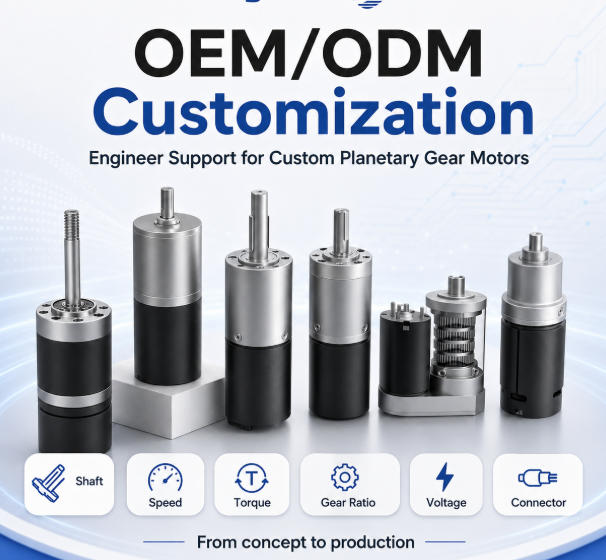
- Planetary Gear Reducer Motors: Deliver high torque density in a compact coaxial footprint with low backlash, making them ideal for precision motion control and micro-automation.
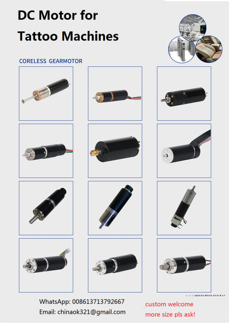
- Micro DC Gear Motors (Spur, Flat, and Planetary): Designed for compact OEM devices, medical devices, smart locks, and small motorized actuators.
3-Step Selection Guide for Gear Reducer Motors
To select the correct gear motor model for your equipment, evaluate three core mechanical parameters:
1. Calculate the Required Gear Reduction Ratio
Determine the required driven speed of your machine relative to the base motor speed:
$$\text{Deceleration Ratio} = \frac{\text{Input Shaft Speed (Motor RPM)}}{\text{Output Shaft Speed (Required Machine RPM)}}$$
2. Determine Required Operating Torque
Calculate the continuous and peak load torque needed by the driven machine. Cross-reference this figure against the manufacturer’s rated output torque tables to ensure the internal gear train can handle the mechanical stress without tooth failure.
3. Specify Integrated Auxiliary Options
Identify any specialized electrical or mechanical requirements for your application:
- Power-off electromagnetic safety brakes or holding brakes
- Variable frequency drive (VFD) compatibility or integrated speed controllers
- Customized housing materials (die-cast aluminum or heavy cast iron)
- Feedback devices such as magnetic or optical encoders for closed-loop positioning
Essential Installation, Safety, and Maintenance Guidelines
Proper installation and maintenance directly impact gear motor service life and operator safety. Follow these field-proven practices:
Electrical and Mechanical Safety Precautions
- Grounding Requirements: Always connect the motor frame to a dedicated earth ground in accordance with local electrical safety regulations.
- Mechanical Fastening Check: Verify that all mounting bolts, shaft keys, couplings, and power transmission components are fully secured prior to initial startup.
- Capacitor Discharge for Single-Phase Units: Single-phase AC reduction motors retain electrical energy in their start/run capacitors after power is cut. Fully discharge the capacitor or ground the terminals before servicing.
- Auxiliary Cooling for Low-Speed Inverter Operation: When driving a gear motor via a variable frequency drive (VFD) at low operating frequencies, internal fan cooling drops significantly. Install an independent powered cooling fan to prevent thermal overload.
Hand-Soldering Protocol for Motor Terminals
When soldering wire leads to small brushed DC gear motor terminals:
- Maintain soldering iron temperatures between 350°C and 400°C.
- Complete each joint within 2 to 3 seconds.
- Warning: Prolonged heat exposure transfers down the terminal pin, which can melt internal brush holders and plastic connection housings.
Shaft Handling and Mechanical Anti-Backdrive Protection
- Do Not Force the Output Shaft: Never rotate the output shaft manually by hand during installation or alignment. Back-driving turns the gearbox into a speed multiplier and forces the electric motor to act as a generator, risking gear damage or voltage backfeed into driver electronics.
- Shaft Machining Limits: Do not alter, grind, or machine the output shaft without factory approval, as radial or axial forces can align incorrectly and strip internal gear teeth.
Managing Motor Lifespan, Thermal Risk, and Electrical Phenomena
Recognizing electrical and thermal behaviors during operation helps prevent premature drive failure:
- Managing Frequent Stalls and Overloads: While heat generated under nominal load reaches thermal equilibrium, repeated stalling or heavy overload rapidly spikes winding temperatures. This degrades coil varnish insulation and eventually causes armature burn-out.
- Preventing Short Circuits in Low-Speed Carbon Brush Motors: Operating brushed DC motors at low speeds over long periods causes shed carbon dust to collect in commutator slots rather than clearing away cleanly. Providing your working voltage and target RPM allows engineers to select optimized brush compounds and commutator geometry.
- Dynamic Braking and Motor Inertia: When power is cut, rotational inertia causes the motor shaft to coast for a few seconds. Connecting the positive (
+) and negative (-) terminals together instantly activates dynamic braking via reverse generator current. Note that frequent dynamic braking creates high momentary current spikes, which can shorten total motor service life.
Technical Consultation for Custom Motor Requirements
When selecting a micro DC gear motor or precision planetary drive from our lineup at www.coreless-motor.com, providing complete application details allows our engineering team to recommend the ideal drive configuration.
Selection Recommendations by Form Factor:
- For Low Speed with Light-to-Moderate Torque: Select micro gear motors with gearbox diameters under 37mm.
- For Low Speed with High Torque Output: Select gearheads with outer diameters above 37mm.
- For Ultra-High Torque in Restricted Spaces: Choose Planetary Gear Motors or Flat-Shaped Gearhead Drives.
- For Space-Saving Right-Angle Drives: Choose Worm Gear Motors for high reduction ratios, quiet meshing, and self-locking capabilities.
To request a custom motor evaluation, submit your operating voltage, target load speed (RPM), continuous output torque, and dimensional envelope to our technical sales team at www.coreless-motor.com.
📌 We accept customized specification/parameters/drawings, contact us now for your requirement. Our engineering team will be delighted to make samples for you.
-
📧 Email Us: chinaok321@gmail.com
-
📱 WeChat/Mob: +8613713792667 ( our Whatsapp is blocked, please don't use whatsapp, just email, thanks)